International Journal of Agriculture, Environment and Biotechnology
Citation:
DOI: 10.30954/0974-1712.03.2020.4
![]()
AGRICULTURAL ENGINEERING
Development of Circular Flumes for Low Discharges Using Critical Flow Concept
ABSTRACT
In the water scarce situation, measurement of flow in open channel reduce the pressure on water resources and promotes the better utilization of water. The present study aimed at developing critical flow circular flume with rectangular centre contraction. The circular flume was designed by placing rectangular block in a U- shaped channel. Six flumes were fabricated with different contractions and throat lengths (30%, 40% and 50% contractions and 15 cm and 30 cm throat lengths). Water surface profiles were collected for four discharges (6, 9, 12 and 15 Lps). Critical depths were computed and located on the water surface profiles. The study revealed that the critical flow conditions occurred at 15, 12 Lps in all six flumes. At low discharges and low contractions critical flow conditions not occurred in the throat. The head discharge equations were derived the computed discharges are compared with the actual discharges. The highest deviation observed in case of Flume -1 (-8.344%). 90 % of the errors are within the range of ± 5%.
Highlights
 Measurement of flow in open channel with critical flow concept
High accuracy of flow measurement
Suitable for low discharges in field channels
Keywords: Open channel, Water measurement, flume, Critical depth, Accuracy
As per the water economics, the irrigated agriculture sector is the largest user of water. Measuring flow from a reservoir is a common application, where open-channel flow measurement comes into with known depth-to-flow relationship. Irrigation water measuring devices are concerned with the water supply from an irrigation canal / channel or some other source of surface water. The specific purpose is to ensure set amount of water has been delivered to a user. It is not only essential for the water user and to ensure that they use their full allotment, but also to ensure that they do not exceed their allotment. Good water measurement and management practices would (i) Enhance the water productivity of different crops (ii) Prevent loss of water (iii) deal efficiently with water-logging control and salinity areas (iv) Bring more areas under cultivation with less water. Once a weir or flume is installed, a measurement of the depth of the water is used to calculate flowrate. The development of on-farm irrigation requires economical usage of irrigation water with the rapid increase in use of all available water resources and increased costs.
How to cite this article: Sai Sucharitha, Y., Krupavathi, K., Satyanarayana, T.V. and Edukondalu, L. (2020). Development of Circular Flumes for Low Discharges Using Critical Flow Concept. IJAEB, 13(3): 285–292.
Source of Support: Dr. NTR. College of Agricultural Engineering, Bapatla; Conflict of Interest: None ![]()
The use of concept of critical flow in weirs and flumes is a common method of measuring flow in open channel. Creating critical flow makes it possible to measure the depth and calculate the flow rate, thus simplifying the monitoring of flow rate. Many measuring and regulating devices have been developed by earlier researchers (Samani, 2017; Hoda et al. 2017; Carollo et al. 2016; Ghare et al. 2014; Krupavathi et al. 2012(a)). All of them do not satisfy the concomitant requirements of simplicity, sturdiness, reasonable accuracy, adoptability to any cross-sectional shape of channels and low head loss leaving enough scope for further research and development in the field of small measuring structures. The analysis of difficult in the rectangular/curvilinear flow, the complication in fabrication, the errors in installation, the economy and the sensitivity towards submergence have limited the use of these flumes. Hence, a need arises to lay emphasis on development of simple critical flow flumes by creating contraction at the middle of the section and not from the bottom so that obstructions to any debris and deposition of silt/any debris on upstream side is avoided. The formation of critical flow condition in the throat section is important characteristic which should be study (Krupavathi et al. 2012(b)). The present study is planned to design and develop a rectangular contracted flume in U channel. The flume is tested for its occurrence of critical flow conditions and flow characteristics in developed flumes.
MATERIALS AND METHODS
Experimental Setup
The experimental set-up consists mainly of a large Hydraulic flume with motorized bed slope alteration facility (Commercial make) existing in the Fluid Mechanics and Hydraulics laboratory of the Department of Soil and Water Engineering, Dr. N.T.R. College of Agricultural Engineering, Bapatla. The college is one of the very few engineering colleges in AP to have this particular type of the hydraulic flume. In fact, it is state-of-the-art facility in the college which paved the way to conduct all experiments of this study (Fig 1).The availability of normal flow in hydraulics laboratory is between 5 Ls-1 to 27 Ls-1. The maximum flow available in the hydraulics laboratory is 27 Ls-1. Because of practical application of flow regulation with gates and outlets, the experiments were planned to conduct at four different discharges of 15 Ls-1, 12 Ls-1, 9 Ls-1 and 6 Ls-1. To conduct experiment at above particular flows, the flow rates at various gauge levels were measured volumetrically. The average of 3 to 4 simultaneous measurements was taken as average actual discharge with that outlet setup.
The total length of hydraulic flume is 10 m long having a channel cross section of 0.3 m width and 0.6 m depth (Fig. 2). Two gates placed at either ends of flume are operated by rack and pinion arrangement. A trolley with point gauge arranged on the top frame of flume runs throughout the length of test section. A 1 mm interval graduated scale fixed at the top of the frame indicates the distance of trolley from the measuring device. The distance from the measuring device is important based on theoretical consideration and accuracy of head measurement. A point gauge provided on the trolley in combination with the graduated scale enables to measure the head causing flow in the flume at any desired distance from the measuring weir or flume.
The recirculation system of components includes sump, rectangular contractions, pipe inlet, hydraulic flume, collecting tank. Two mono block pumps (each 5 Hp) placed nearer to sump delivers water to the hydraulic flume through inlet pipe.
Preparation of critical flow flumes
The development of models based on the modification of circular flume originally proposed by Hager (1988) and tested by Samani (2017). In the present experiment, the bottom circular cylinder used by previous scientists was replaced with ‘U’ shape. The ‘U’ shape was selected because the top half cylinder of the original circular flume has no use in the design as reported by Gerald (2015). The U channel was constructed by bending Flexi glass into 30 cm diameter semi-circle at the bottom and 15 cm straight vertical portion extended on both sides above the semi-circle. The semi-circular Flume (U shape) provides smooth and parallel streamlines without the effects of flow separation at the throats. The semi-circular flume was installed in the hydraulic flume with side walls of the flume attached to the sidewalls of the rectangular hydraulic flume. The bed of hydraulic flume was kept perfectly horizontal and free of water before installation.
The rectangular middle contraction is used to obtain critical flow conditions without any bottom contraction in the semi-circular channel. The contraction was achieved by placing a rectangular block in a perpendicular position in the middle of the section (Fig. 2). Six flumes with three different contractions and two lengths of throat section were prepared. The contractions include 9 cm, 12 cm, 15 cm and two throat lengths are 30 cm and 15 cm. The detailed dimensions of the six flumes are presented in Table 1. The models were prepared with a 3 mm flexible glass sheet (Fig. 3). The prefabricated rectangular contractions were installed at the middle in semi-circular bottom flume by leaving a 0.1 m from the downstream end to make the so called full-fledged circular critical flow flumes in the present study.

Design and Planning of Experiments
A scheme of experiments was planned and performed by fixing a set of rectangular contraction along with semi-circular channel to form one critical flow flume at a distance of 2 m from the end of tail gate. The levels of experimental variables chosen for the study are as follows:
♦ Flume types: Six flumes with three contractions and 2 throat lengthswere selected (Table 1).
♦ Discharges: 4 15Lps, 12Lps, 9Lps and 6Lps
♦ Free flow conditions: 3 30%, 40% and 50%
Starting with the 30% contraction and 15Lps discharge, the water surface profiles were recorded. The process of recording the water surface profiles has been repeated with remaining three discharges of 12Lps, 9Lps and 6Lps and four different submergence conditions for each flume type. The circular contracted flume-1 has been replaced by flume-2 flume-3, flume-4, flume-5 and flume-6 subsequently taking all precautions as in the installation of flume-1.A theoretical criterion for critical flow by definition is the state of flow the specific energy is minimum for a given discharge. From Bernoulli’s equation,
Where, E = Specific Energy, Q = Volume rate of flow, V = Average Velocity, A = Cross-sectional area of flow, g = Acceleration due to gravity, y = water depth
At critical flow conditions 
Therefore,
The water area dA near the surface is equal to time, then the equation becomes,
The above equation at the critical state of flow, therefore gives

The subscript ‘c’ relates to critical condition. Critical depths for four discharges have been computed from equation (3) and presented in Table 2. The critical depths have been located on plotted water surface profiles.
RESULTS AND DISCUSSION
The computed critical depths in the previous section were used to find the formation of critical flow conditions in the throat section and position of the critical depth were recorded from the brink depth.
Formation of critical flow conditions
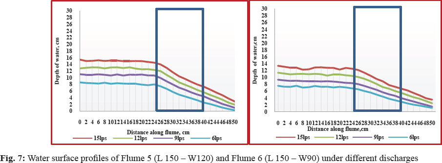
The water surface profiles of all individual flumes are shown in Fig. 5 to Fig. 7 and the location of critical depth is shown in Table 3. It was observed that with the decreasing the flow for a particular contraction, the height of water surface decreased. It was observed that the flow in the throat of circular flume was not uniform over entire flume and is gradually varied till end of the flume. The flow profile in the throat of the flume was found to depend on the discharge, head of water, length of the crest in the direction of flow. The flow of water in the flume throat section is divided equally into two parts around the middle contraction.
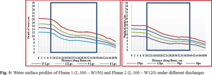
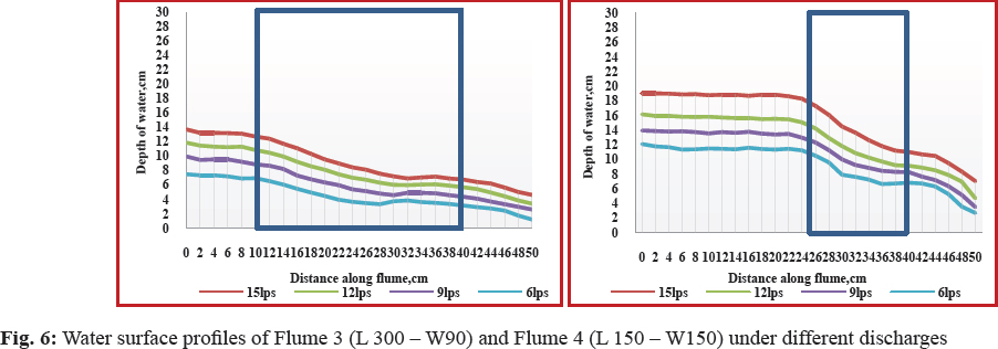
For flume -1, the distance of critical section varied from 27 cm to 7 cm from the brink section. For highest discharge of 15Lps, the location of the critical depth occurred at 27cm from the brink for free flow condition. It occured at a distance of 23 cm for a discharge of 12Lps. For the discharge of 9Lps and 6Lps critical section occurred at 12 cm and 7 cm respectively from the end of throat section. For flume -2, with the highest discharge of 15Lps, the location of the critical depth occurred at 20cm from the brink for free flow condition. It occurred at only one location at a distance of 2 cm for a discharge of 12Lps. For the discharge of 9Lps and 6Lps critical section occurred at 1.5 cm and 1 cm respectively from the end of throat section. For flume -3, For highest discharge of 15Lps, the location of the critical depth occurred at 11.5 cm from the brink for free flow condition. It occurred at a distance of 0.5 cm from brink for a discharge of 12Lps. For the discharge of 9Lps and 6Lps critical section was not occurred from the end of throat section. For flume -4, the distance of critical section varied from 13 cm to 3 cm from the brink section. For highest discharge of 15Lps, the location of the critical depth occurred at 13 cm from the brink for free flow condition.
For flume -5, with the highest discharge of 15Lps, the location of the critical depth occurred at 8.8 cm from the brink for free flow condition. Lc occurred at a distance of 1.5 cm for a discharge of 12Lps. For circular contraction Flume 6 (L 150 and W 90 mm) the discharge of 9Lps critical section occurred at 1.0 cm from the end of throat section. No critical section occurred for other two discharges. This reveals that theis suitable for the discharge range of 12 to 15 Lps.
It was observed from the above results that critical section occurred at only one location in the throat section. For none of the flume conditions, the critical section occurred at any fixed location for the range of flows tested. Since the critical sections have been found to occur in the throat of 15Lps and 12Lps discharge range for all the flumes tested, the developed flumes can be used for measurement of water (in the discharge range of 12–15Lps) as there exists a unique head-discharge relationship. From the results, it was clear that for a particular contraction, the critical depth increased with increase in discharge. For a particular discharge, the critical depth was found to increase with increase in contraction (Sterling et al. 2000; Sahnaz et al. 2008; Krupavathi et al. 2012(a)).
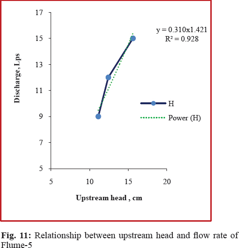
Relation between Head and discharge under free flow conditions
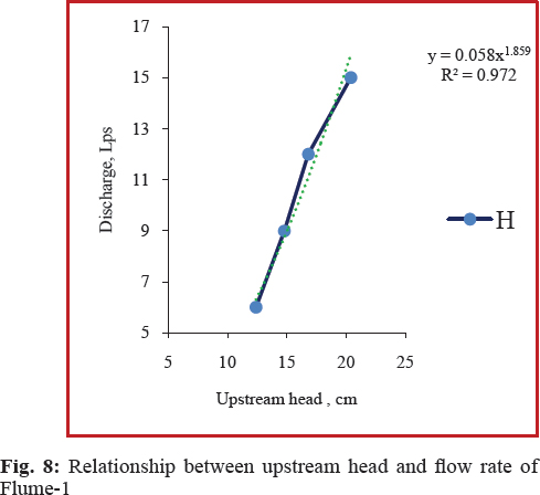
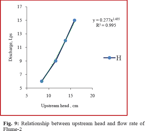
The relation between measured flow rates and corresponding upstream heads under free flow conditions for each flume is shown in Fig. 8 to 11. .From the graphs, it was observed that the upstream head increased with increase in discharges. The results showed that a generalized flow equation in a flume (Samani, 2017), which can be developed for each flume as
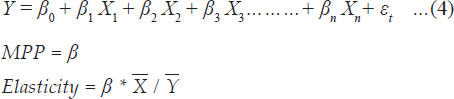
Where, Q = Discharge in Lps; H = Upstream head in mm; and c and n = Calibration coefficients.
Calibration coefficients ‘c’ and ‘n’ are constants for a particular type of flume. The calibration coefficients of the equation for each flume are shown in Table 4. The calibration coefficients of the same contraction have values nearer to each other. The R2 values of equation of developed flumes varied as 0.972, 0.992, 0.9904 and 0.928 for Flume-1, Flume-2, Flume -4 and Flume -5. This shows that the proposed general equation is useful for measuring the discharge with the measurement of upstream depth.
To evaluate the performance of circular contraction critical flow flumes and to estimate the accuracy through the deviations in discharges the discharges from the flumes of all contractions and throat lengths computed from Eq. (4) were compared with actual discharges (Table. 5).
In case of Eq. (4) for Flume-1, the average deviations in discharge (Table 5) are -5.615%, -8.344%, -2.858% and 4.710 % at 15 Lps, 12 Lps and 9Lps and 6 Lps under free flow condition. For circular contracted Flume-2, the per cent deviations varied between -0.198 % to 3.582 %. For Flume - 4 and Flume -5, the highest deviations are - 2.93 % and -8.106 %. All the errors are in between ± 10%. The results are on par with Hoda et al. (2017). This shows that the developed equation for all flumes are in agreement with measured discharges. The highest deviation observed in case of Flume -1 (-8.344%). Compared to flumes with 15 cm throat length, flumes with 30 cm throat length performed well at a particular contraction. However, the errors are low in case of throat 50% contraction and 15 cm throat length flume followed by flume with 40% contraction and 30 cm throat length.
CONCLUSION
Six circular flumes developed by varying the contractions and throat lengths in a U shaped channel were studied in detail. The developed flumes tested for four discharges conditions. The results of the study revealed that critical depth occurred at a section little distance from the upstream end in 50 % contraction cases, but it does not occur at any fixed location. The location of critical depth moved towards the downstream end with decrease in discharge. At the location of critical section moves in upstream direction as the discharge is increased and it was nearer to the brink section for very low discharges. The critical section for parallel flow moves upstream or downstream with change of discharge and at no single section the critical depth occurred for any two discharges. This is because the water surface profiles do not bear the same geometric relationship to flow boundaries and hence complete dynamic similarity in the shapes of water surface profiles between any two discharges is not possible. No critical sections at low discharges and low contractions. The 90% of errors are in the range of ± 5%. Finally, it was concluded that the developed flumes with more than 40% contraction are useful for measurement of discharges with high accuracy.
REFERENCES
Carollo, F.G., Stefano, C.D., Ferro, V. and Pampalone, V. 2016. New stage-discharge equation for the SMBF flume. Journal of Irrigation and Drainage Engineering, 142(5): 1–7.
Gerald, R., Ontkean, Lloy and Healy, H. 2015. Impact of non-level operation of a circular flume on discharge measurements. The Canadian Society for Bioengineering, 15(120): 1–10.
Ghare, D. and Badar, AM. 2014. Experimental studies on the use of mobile cylinders for measurement of flow through rectangular channels. International Journal of Civil Engineering, 12(4): 1–9.
Hager, H. 1988. Mobile Flume For Circular Channel. Journal of Irrigation and Drainage Engineering, 114: 520–534.
Hoda, A.M., Khadr, M. and Rashwan, I.M.H. 2017. Mobile flume for inverted semicircular open channel. Mansoura Engineering Journal (MEJ), 42(4): 1–9.
Krupavati, K., Satyanarayana, T.V. and Hemakumar, H.V. 2012 (a). Performance testing of semi-circular contraction critical flow flumes for field channels. Journal of Mechanical and Civil Engineering (IOSR), 1(5): 01–07.
Krupavathi, K., Satyanarayana, T.V. and Hema Kumar, H.V. 2012 (b). Effect of submergence on flow characteristics and accuracy of measurement in semi-circular contraction critical flow flumes. International Journal of Agricultural Engineering, 5(2): 268–272.
Samani, Z. 2017. Three simple flumes for flow measurement in open channels, Journal of Irrigation and Drainage Engineering, 2: 2–5.
gahnaz, T., Firat, C.E. and Ger, A.M. 2008. Use of brink depth in discharge measurement. Journal of Irrigation and Drainage Engineering, 134(1): 89–95.
Sterling, M. and Knight, D.W. 2000. The free overfall as a flow measuring device in a circular channel. Water and Maritime Engineering, 148: 235–243.